The fundamental data structure at the heart of The Sentinel's tile landscape
As described in the deep dive on Cartesian coordinates, the landscape in The Sentinel consists of a tiled area of 31x31 tiles. You can think of it like an undulating chess board that's sitting on a table in front of us, going into the screen.
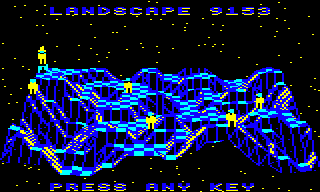
For example, here's the preview for landscape 9153, which enjoys an awful lot of undulation:
The shape of the landscape is defined by the altitude of the corners of each tile, so that's a 32x32 grid of altitudes, one for each tile corner.
This information is stored in the tile data table at tileData, which contains one byte for each tile, so that's a total size of 32x32 = 1024 bytes. At 1K in size, this makes the tileData table the biggest individual data table in the game.
We can refer to individual tiles by using a tile coordinate of the form (xTile, zTile). The x-axis runs along the front edge of the landscape, from left to right, while the z-axis goes into the screen from front to back, away from us. The GetTileData routine takes a tile coordinate as an argument and returns the tile data.
The single byte of tile data comes in two formats: one format for when there is no object on the tile, and another format for when there is an object on the tile. Both of these formats co-exist in the same data table, in a rather elegant use of space. Let's take a look at both formats.
No object on tile
-----------------
If there is no object placed on the tile, then the data contained in each byte is as follows, split into the high nibble in bits 4 to 7, and the low nibble in bits 0 to 3:
                   7654 3210
                   aaaa ssss
                    ^     ^
                    |     |
                    |     |
             Altitude     Shape
              1 to 11     0 to 15
       %0001 to %1011     %0000 to %1111
To break this down:
- The low nibble of each byte contains the tile shape %ssss, which describes the layout and structure of the landscape on that tile (0 to 15). See the deep dive on tile shapes for information on the different types of tile shape.
- The high nibble of each byte contains the altitude %aaaa of the tile corner in the front-left corner of the tile (i.e. the corner closest to the origin of the landscape). We call this tile corner the "anchor". The altitude is in the range 1 to 11, so the top nibble never has both bit 6 and 7 set.
You will often see tile data being split into two nibbles to extract the tile shape and altitude, though this only applies when bits 6 and 7 are not both set. If they are, then there is an object on the tile, which brings us to the second data format.
Object on tile
--------------
If there is an object placed on the tile, then the data contained in each byte is as follows, split into bits 6 and 7, and bits 0 to 5:
                   76 543210
                   11 nnnnnn
                          ^
                          |
                          |
                          Object number
                          0 to 63
                          %000000 to %111111
To break this down:
- Bits 0 to 5 contain the number %nnnnnn of the object on the tile (0 to 63). If there are multiple objects stacked on the tile, this is the number of the object on the top of the stack. See the deep dive on stacking objects for more details on object stacks.
- Bits 6 and 7 of the byte are both set when there is an object on the tile.
We can therefore test for the presence of an object on a tile by checking whether both bit 6 and 7 are set (as empty tiles have the tile altitude in the top nibble, and this is in the range 1 to 11). Only flat tiles can contain objects, so in this case we don't need to store the tile shape, as we know it is shape 0 (flat). As for the altitude, this is no longer stored in the tile data, but we get around that by allocating the tile altitude to the object instead.
As each tile is defined by a tile corner and a shape, we tend to use the terms "tile" and "tile corner" interchangeably, depending on the context. That said, for the tile corners along the furthest back and rightmost edges of the landscape (i.e. when xTile = 31 or zTile = 31), the shape data is ignored, as there is no landscape beyond the edges.
Table layout
------------
The tileData table is not laid out in a particularly obvious manner. Instead of being stored in a standard x-axis by z-axis structure, it is stored as an interlaced set of tile columns. There doesn't seem to be an obvious programmatic reason for this; it could be a simple trick to hide the landscape structure from anyone trying to poke through the game memory to work out how to hack it, but it's hard to tell.
Specifically, the tile data table at tileData is made up of sequences of 32 columns of tile corners going into the screen, where each column goes from zTile = 0 to 31 along the same x-coordinate, with the columns interleaved in steps of 4 like this:
   &0400-&041F = 32-corner column going into the screen at xTile =  0
   &0420-&043F = 32-corner column going into the screen at xTile =  4
   &0440-&045F = 32-corner column going into the screen at xTile =  8
   &0460-&047F = 32-corner column going into the screen at xTile = 12
   &0480-&049F = 32-corner column going into the screen at xTile = 16
   &04A0-&04BF = 32-corner column going into the screen at xTile = 20
   &04C0-&04DF = 32-corner column going into the screen at xTile = 24
   &04E0-&04FF = 32-corner column going into the screen at xTile = 28

   &0500-&051F = 32-corner column going into the screen at xTile =  1
   &0520-&053F = 32-corner column going into the screen at xTile =  5
   &0540-&055F = 32-corner column going into the screen at xTile =  9
   &0560-&057F = 32-corner column going into the screen at xTile = 13
   &0580-&059F = 32-corner column going into the screen at xTile = 17
   &05A0-&05BF = 32-corner column going into the screen at xTile = 21
   &05C0-&05DF = 32-corner column going into the screen at xTile = 25
   &05E0-&05FF = 32-corner column going into the screen at xTile = 29

   &0600-&061F = 32-corner column going into the screen at xTile =  2
   &0620-&063F = 32-corner column going into the screen at xTile =  6
   &0640-&065F = 32-corner column going into the screen at xTile = 10
   &0660-&067F = 32-corner column going into the screen at xTile = 14
   &0680-&069F = 32-corner column going into the screen at xTile = 18
   &06A0-&06BF = 32-corner column going into the screen at xTile = 22
   &06C0-&06DF = 32-corner column going into the screen at xTile = 26
   &06E0-&06FF = 32-corner column going into the screen at xTile = 30

   &0700-&071F = 32-corner column going into the screen at xTile =  3
   &0720-&073F = 32-corner column going into the screen at xTile =  7
   &0740-&075F = 32-corner column going into the screen at xTile = 11
   &0760-&077F = 32-corner column going into the screen at xTile = 15
   &0780-&079F = 32-corner column going into the screen at xTile = 19
   &07A0-&07BF = 32-corner column going into the screen at xTile = 23
   &07C0-&07DF = 32-corner column going into the screen at xTile = 27
   &07E0-&07FF = 32-corner column going into the screen at xTile = 31
To implement this structure, the GetTileData routine converts a tile coordinate of (xTile, zTile) into an address and offset using this algorithm:
  tileDataPage(1 0) = tileData + (xTile mod 4) * &100

  Y = (xTile div 4) * &20 + zTile
This gives us the following result:
- The address in tileDataPage(1 0) gives the page within tileData for the tile anchored at (xTile, zTile), and is always one of &0400, &0500, &0600 or &0700 because (xTile mod 4) is one of 0, 1, 2 or 3.
- The value of Y is the offset within that page of the tile data for the tile anchored at (xTile, zTile).
We can therefore fetch the tile data for the specified tile using Y as an index offset from tileDataPage(1 0), using a LDA (tileDataPage),Y instruction.
Don't worry, I think it's supposed to be confusing...