Details of all the 3D objects, from trees and boulders to the Sentinel itself
The Sentinel's incredible 10,000 landscapes might be the most talked-about aspect of the game, but when it comes to gameplay, it's all about the 3D objects.
There are ten different types of object in total. Three of these are large blocks that are used to draw the 3D text on the title screens; these are included here, but for more information about how they are used, see the deep dive on drawing 3D text using blocks.
The other seven are the game objects. There are three types of enemy object: the Sentinel, the sentry and the meanie. Then there's the player, who's represented by the robot. And then there are the various inanimate objects: the boulder, the tree and the Sentinel's tower.
First let's take a look at what these objects look like, and then we can talk about how these objects are defined and displayed.
Object definitions
------------------
In the following table, the objects are all shown at the same scale, apart from the 3D text blocks, which are shown at half-scale.
I've captured each object in-game in two different palettes: the first is the palette for landscape 0000 (blue, black, white, green), and the second is the palette from the title screen (blue, black, red, yellow).
To try to show the shape of each object, the first two images have the object facing towards us but looking slightly to our left, while the next two images have the object turned by 90 degrees to the left, so the object is facing left and slightly away from us (from the perspective of the object, they have just turned 90 degrees to their right for this second mug shot). Some of the more symmetrical objects don't look particularly different side-on, but I've left all of the different rotations in for consistency.
| Object | Examples |
|---|---|
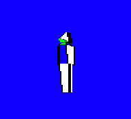
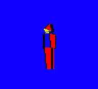
| Robot Object type: 0 Polygons: 0 to 26 (27 polygons) Points: 0 to 28 (29 points) Object definition: objRobot |
Facing towards us and slightly to our left:
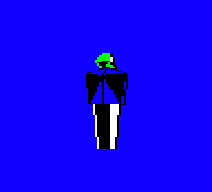
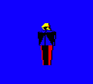
Facing to the left and slightly away from us:
|
| Sentry Object type: 1 Polygons: 27 to 51 (25 polygons) Points: 29 to 50 (22 points) Object definition: objSentry |
Facing towards us and slightly to our left:
Facing to the left and slightly away from us:
|
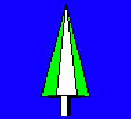
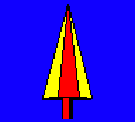
| Tree Object type: 2 Polygons: 52 to 66 (15 polygons) Points: 51 to 67 (17 points) Object definition: objTree |
Facing towards us and slightly to our left:
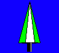
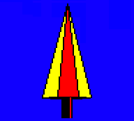
Facing to the left and slightly away from us:
|
| Boulder Object type: 3 Polygons: 67 to 76 (10 polygons) Points: 68 to 75 (8 points) Object definition: objBoulder |
Facing towards us and slightly to our left:

Facing to the left and slightly away from us:

|
| Meanie Object type: 4 Polygons: 77 to 101 (25 polygons) Points: 76 to 93 (18 points) Object definition: objMeanie |
Facing towards us and slightly to our left:
Facing to the left and slightly away from us:
|
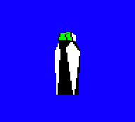
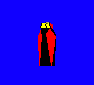
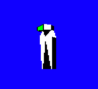
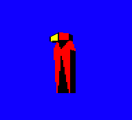
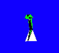
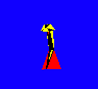
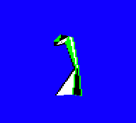
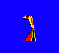
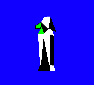
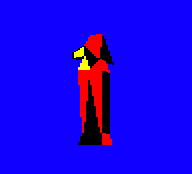
| The Sentinel Object type: 5 Polygons: 102 to 136 (35 polygons) Points: 94 to 123 (30 points) Object definition: objSentinel |
Facing towards us and slightly to our left:
Facing to the left and slightly away from us:
|
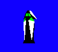
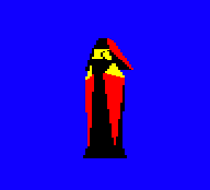
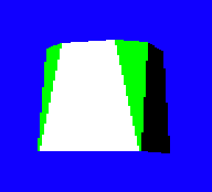
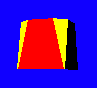
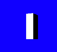
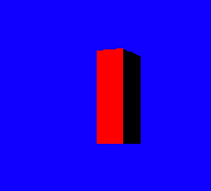
| The Sentinel's tower Object type: 6 Polygons: 137 to 147 (11 polygons) Points: 124 to 135 (12 points) Object definition: objTower |
Facing towards us and slightly to our left:
Facing to the left and slightly away from us:
|
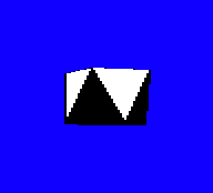
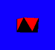
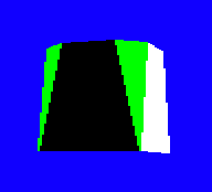
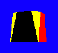
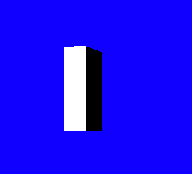
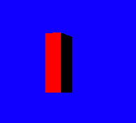
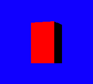
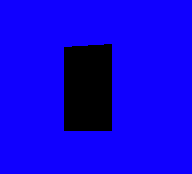
| 3D text block No block (left) Block (right) Object type: 7 Polygons: 148 to 151 (4 polygons) Points: 136 to 143 (8 points) Object definition: objTextBlock |
Facing towards us and slightly to our left:
Facing to the left and slightly away from us:

|
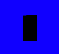
| 3D text block Block (left) No block (right) Object type: 8 Polygons: 152 to 155 (4 polygons) Points: 144 to 151 (8 points) Object definition: objTextBlock |
Facing towards us and slightly to our left:
Facing to the left and slightly away from us:
|
| 3D text block Block (left) Block (right) Object type: 9 Polygons: 156 to 159 (4 polygons) Points: 152 to 159 (8 points) Object definition: objTextBlock |
Facing towards us and slightly to our left:
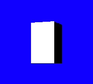
Facing to the left and slightly away from us:
|
Let's take a look at how these objects are defined, and what the figures in the above table actually mean.
3D object definitions
---------------------
The 3D objects in The Sentinel are implemented in a fascinating way that lends itself nicely to the game's unique angle system and the enemies' rotational gameplay. In order to understand the following, I recommend you take a look at the deep dive on pitch and yaw angles, as angles literally lie at the heart of the 3D objects in The Sentinel.
Games that contain 3D objects typically define the shapes of those objects in terms of Cartesian coordinates. Elite, for example, defines its ships using vertices, faces and edges, where the vertices are points with coordinates in the familiar (x, y, z) Cartesian space (see my Elite deep dive on ship blueprints for details).
When it comes to previous Geoff Crammond games, Aviator defines its 3D objects in terms of lines and points, again using Cartesian coordinates (see my Aviator deep dive on 3D objects for details). On the other hand, Revs doesn't actually contain any 3D objects, but instead it creates pretend 3D objects from 2D shapes (see my Revs deep dive on drawing a 3D car from 2D parts).
The Sentinel, though, is different, because it defines its object points using cylindrical coordinates, which are then used to define polygons in 3D space that make up the objects we see on-screen. The advantage of this system is that it makes it almost trivial to rotate objects through yaw angles around their centres, which is pretty important when your game is based on enemies scanning a 3D landscape by rotating around to their left or right.
Let's look at the three levels of object definition in turn: points, polygons and objects.
Points
------
At the fundamental level, objects are made up of points in 3D space. These points are grouped into polygons to form objects, which we'll cover later, but for now let's just consider the points, as their implementation is interesting.
There are 160 points defined in The Sentinel, numbered from 0 to 159, and between them they specify the coordinates of all the points within all the 3D objects. The objPointRange table defines the range of point numbers that is used for each object, so object type 0 (the robot) is constructed using points 0 to 28, while object type 4 (the meanie) uses points 76 to 93. These ranges are also shown in the table of objects above.
Each point's coordinate is defined using three values, but they aren't the normal (x, y, z) Cartesian coordinates that you might expect. Instead each point is defined using cylindrical coordinates, which are a bit like polar coordinates that are extruded up or down from the object's origin (see the Wikipedia article on the cylindrical coordinate system for more details). These coordinate values are stored in the following tables, each of which contains the specified values for all 160 points:
- The objPointYaw table contains the polar yaw angles for all of the points in all of the objects.
- The objPointDistance table contains the polar distances for all of the points in all of the objects.
- The objPointHeight table contains the height of all of the points in all of the objects, relative to the object's origin.
To visualise how these coordinates work, consider an object such as the Sentinel, like this:
Now imagine a vertical rod running through the Sentinel from head to toe, going straight through the middle of the Sentinel object. This is the height axis, and it points upwards, so height values increase as we move up the rod. Somewhere near middle of this rod is the object's origin, at height 0, and the height is negative below the origin and positive above the origin.
To find out where a point lies within the object, we first take the point's height from the objPointHeight table and work out where this lies on our vertical rod. We then consider the horizontal plane passing through this height, and apply the point's yaw angle and distance within this plane using the standard polar coordinate system to give us our point in 3D space. It's as if we are sketching the polar coordinates on a horizontal piece of paper that passes through the rod at the specified height, and with the rod being the origin of the 2D polar coordinate system.
If polar coordinates aren't your thing, let's explain this in a different way, by considering this overhead view of our Sentinel object, with its beady eyes pointing upwards in this diagram. This is us looking down onto the top of its head, and the vertical rod is the + in the middle:
           0
     -32   |   +32
        \  |  /
         \ | /                 ^
          \|/                  |
  -64 -----+----- +64          +   Overhead view of the Sentinel,
          /|\                      looking forwards
         / | \
        /  |  \
     -96   |   +96
          128
If the yaw angle in objPointYaw is 32, then our point is forwards and right of the Sentinel's gaze, so it could be part of the right side of its prominent nose; while if it's -64 then it's directly to the left of the Sentinel, which could be a point on the side of its left foot.
Once we have the angle, we move away from our central rod in this direction, and the distance we move away is given in the objPointDistance table. So the point of the Sentinel's nose will have a bigger distance value than the tuck under its chin, for example.
Finally, the objPointHeight table defines how high the point is within the object, so negative heights will be towards the Sentinel's feet and positive heights will be towards its head. You can think of this stage as extruding the points that we're defining, pulling them away from the origin at the centre of the object by the specified distance.
The beauty of this system lies in the ease of rotation. Enemy objects rotate as they scan the landscape, and the player's robot does the same as it pans the landscape view, so rotation is core to the gameplay. In particular, it's yaw rotation that we see with objects, as the 3D objects rotate left and right but they don't change shape when they look up and down (though they do change the pitch of their gaze in-game, it's just not shown graphically).
The process for drawing a 3D object is described in the deep dive on drawing 3D objects, but the core of the calculation is to take the object's position, yaw rotation and object definition, and then calculate where each point within the object appears on-screen, so we can draw the relevant polygons. Because we use cylindrical coordinates rather than Cartesian coordinates, it's no more effort to do this calculation when the object is rotated - we simply add the object's yaw rotation to the objPointYaw angles in the object definition, and that will turn the object in space. If we had to rotate each of the object points using Cartesian coordinates, this would be a pretty complicated calculation, but in the Sentinel it effectively takes zero extra effort.
Of course, there is still plenty of heavy maths involved in The Sentinel despite this particular simplification, but implementing object points as cylindrical coordinates does make yaw rotations very easy indeed.
Polygons
--------
Each object's shape is made up of multiple polygons. These are the shapes that are actually drawn on-screen.
There are 160 polygons defined in The Sentinel, numbered from 0 to 159, and between them they specify the style and shape of each polygon. The objPolygonRange table defines the range of polygon numbers that is used for each object, so object type 0 (the robot) is constructed using polygons 0 to 26, while object type 4 (the meanie) uses polygons 77 to 101. These ranges are also shown in the table of objects above.
It's worth confirming that, yes, the number of points is the same as the number of polygons - i.e. 160. This is a lovely example of Geoff Crammond squeezing as much data as possible into the small memory footprint of the BBC Micro, because this means the vast majority of point and polygon tables will be 160 bytes long. These therefore fit beautifully into the spare memory after each of the higher-number screen row buffers, which are also 160 bytes long. Because the buffers are spaced out every 320 bytes, just like character rows in screen memory, they create a series of 160-byte gaps that aren't needed for buffering, but they do make a perfect home for the object point and polygon data; see the deep dive on screen buffers for more details.
Each polygon is essentially a collection of points and a set of polygon data. Here are all the tables that store polygon definitions:
- The points in each polygon are stored in the tables objPolygon000 through objPolygon151.
- The objPolygonData table contains various data for object polygons (such as colour, number of sides and drawing phase).
- The objPolygonPhases table contains the phase configuration for each object.
Let's take a look at these in turn.
The points that make up each polygon are stored as sequences of point numbers, with the first point number being repeated at the end of each list; take a look at objPolygon000 for an example. There doesn't seem to be a reason for storing this repeated point number, as we could easily stash the first point number and reuse it again at the end during the drawing process, but perhaps the drawing routines started out supporting open shapes as well as closed polygons, and this is a remnant of that approach; this is a guess, though, and all the polygon point lists have this repeated entry at the end, so all the polygons are closed.
Note that in the polygon point lists, the point numbers are stored with 64 added to them because these values are used as offsets into the drawing tables, and specifically into the table of object point angles that are stored from drawing index 64. Adding 64 at this point means they can be used as offsets from the start of the drawing tables without change, which is convenient but not essential (see the deep dive on the drawing tables for details).
As well as the point data, each polygon has a set of data that determines how we draw it. The data for each polygon is stored in objPolygonData, and is structured as follows:
- Bit 7 is the phase in which to draw this polygon (0 = first phase, 1 = second phase).
- Bit 6 is unused and is always clear.
- Bits 4-5 contain the edge colour (0 to 3).
- Bits 2-3 contain the fill colour (0 to 3).
- Bits 0-1 give the number of sides (0 = three sides, 1 = four sides).
The phase determines the order in which polygons are drawn in each specific object. Most objects are drawn in one phase, but some are drawn in two phases; the number of phases for each object type is defined in the objPolygonPhases table. This can depend on the relative altitude of the object compared to the viewer (for the robot, the sentry or the Sentinel), or it can depend on the object's gaze direction as given in the object's yaw angle (for the meanie). Drawing in phases lets the game support more complex 3D objects; see the deep dive on drawing 3D objects for an explanation of how this works.
The rest of the polygon data is pretty obvious: it defines the number of sides in the polygon, and the colours that are used to draw it. Again, see the deep dive on drawing 3D objects for more information.
Objects
------
As we've seen, each 3D object is defined as a collection of polygons, and each polygon is defined as a collection of points. This data is grouped together in a number of object definitions, one for each object type; for example, the Sentinel object is defined in the objSentinel table, while the meanie object is defined in the objMeanie table.
In practice, the data for each object isn't a list of polygon numbers, but instead it's a list of points, grouped into polygons. So the Sentinel object is formed by sequences of points, all stored in the format described in the previous section (i.e. point numbers with 64 added to them, and with the first point repeating at the end). This sequence of polygon point lists has an address lookup table in the form of the objPolygonAddr(Hi Lo) table, which contains the addresses of each polygon within each object definition.
When deciding how to label the object definitions in my disassembly, I could have gone in another direction. The labels I have added for the objects - i.e. objSentinel, objMeanie and so on - aren't actually used in the code, they are purely there to make it easier for us humans to follow along. The core of each object definition is the range of polygon numbers in objPolygonRange, and the code then uses this range to look up the addresses of the point lists for each of those polygons, which are given in the objPolygonAddr(Hi Lo) table.
This latter table is split into the objPolygonAddrHi and objPolygonAddrLo tables, the contents of which is just a sequence of addresses, starting at objPolygon000 and working through to objPolygon151. There is no concept of object definitions as such, just polygon ranges and a look-up table to the point lists for each of those polygons.
That said, I've added the object-specific labels to make it easier to find the polygon point lists for each object, because this disassembly is for us, not them.
Text blocks
-----------
To finish off, let's take a quick look at the 3D text blocks in objects #7 to #9. These blocks are used to create the 3D text on the title screens, like this:
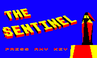
In the object table above, we saw what the blocks look like from the side, where they have red and black faces, but you can't see the tops of the blocks, which are yellow. In the main title screen above, the text shape of "THE SENTINEL" is formed from these 3D blocks. You can think of the text blocks as being laid out on an invisible landscape like a large housing estate, and we're high up in the air looking down from a helicopter at a slightly oblique angle. The letters are formed by the layout of the apartment blocks, with the yellow roofs and red-and-black walls of the text-block apartments forming the pattern of the text.
Each of these objects therefore has the same basic shape - a 3D rectangular block - so as a result we can reuse the same object definition for each of them. That definition is in objTextBlock, and the code uses these same point lists for each of the three objects, but each object has a different point range, and therefore each object has different dimensions.
These dimensions are set up so there's one for each of the three block pairs we need to draw large 3D text on the title screens, as follows:
- Object #7, 3D text block 1, draws no-block (left), block (right). It is made up of polygons 148 to 151, using points 136 to 143.
- Object #8, 3D text block 2, draws block (left), no-block (right). It is made up of polygons 152 to 155, using points 144 to 151.
- Object #9, 3D text block 3, draws block (left), block (right). It is made up of polygons 156 to 159, using points 152 to 159.
See the deep dive on drawing 3D text using blocks for more information about how these three objects are used.
3D object variables and routines
--------------------------------
There are quite a few lookup tables that define the 3D objects. To finish off, here's a list of all of the object definitions:
| Table | Contents |
|---|---|
| objRobot | The list of polygons and points for the robot object (polygons 0 to 26, using points 0 to 28) |
| objSentry | The list of polygons and points for the sentry object (polygons 27 to 51, using points 29 to 50) |
| objTree | The list of polygons and points for the tree object (polygons 52 to 66, using points 51 to 67) |
| objBoulder | The list of polygons and points for the boulder object (polygons 67 to 76, using points 68 to 75) |
| objMeanie | The list of polygons and points for the meanie object (polygons 77 to 101, using points 76 to 93) |
| objSentinel | The list of polygons and points for the Sentinel object (polygons 102 to 136, using points 94 to 123) |
| objTower | The list of polygons and points for the Sentinel's tower object (polygons 137 to 147, using points 124 to 135) |
| objTextBlock | The list of polygons and points for the 3D text block object (polygons 148 to 159, using points 136 to 159) |
And here's a list of tables that define all the points:
| Table | Contents |
|---|---|
| objPointRange | The first and last point numbers for each object |
| objPointYaw | Polar yaw angles for each of the points in each of the objects |
| objPointDistance | Polar distances for each of the points in each of the objects |
| objPointHeight | The height of each of the points in each of the objects, relative to the object's origin |
And finally, here's a list of tables that define the various polygons:
| Table | Contents |
|---|---|
| objPolygonData | Various data for object polygons (colour, drawing phase) |
| objPolygonRange | The first and last polygon numbers for each object |
| objPolygonPhases | The phase configuration for each object |
| objPolygonAddrHi | High byte of the addresses for the lists of polygons and points for each object |
| objPolygonAddrLo | Low byte of the addresses for the lists of polygons and points for each object |
For more information on how the 3D objects are drawn on-screen, check out the deep dive on drawing 3D objects.