How complex 3D objects are drawn using different phases
The Sentinel is famous for its amazing landscapes, where a clever use of projection and perspective enables the relatively sedate 6502 processor to generate a scrollable view that boasts full 3D filled-colour graphics. But the landscape isn't the only game in town, because those lofty peaks and deep valleys are populated with an entire cast of objects, each of them rendered with the same graphical finesse as the surrounding world.
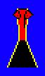
The deep dive on 3D object definitions investigates how the 3D objects are defined as collections of polygons, so it's probably no surprise to find that we can draw those objects on-screen by drawing the individual polygons. If we consider the main title screen:
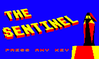
then on the right is the most iconic 3D object from the game: the Sentinel, perched on top of another object, the Sentinel's tower. The title screen pops up fully drawn but there's a noticeable pause before it does so, because as soon as the game starts, the screen is set to use an all-blue palette that hides any drawing activity until the big reveal, at which point the palette switches to the more familiar four colours (see the deep dive on colours and palettes for more details).
While the screen is blanked, there's a lot going on. If we disable the all-blue palette swap and slow things down, then this is what happens behind the curtain:

In this article we're going to look at how the 3D objects are drawn, polygon by polygon. The title text is also drawn using 3D objects, as described in the deep dive on drawing 3D text using blocks, but for now we'll concentrate on how the game draws the rather wonderful in-game objects.
Preparing for the object-drawing process
----------------------------------------
Objects are drawn by the DrawObject routine, which takes the object number of the object we want to draw as an argument. Let's look through this routine to see how it works.
The first step is to calculate the on-screen coordinates for each point in each polygon that makes up our on-screen object. This process is complicated, which is why it has its own dedicated deep dive about calculating angles for drawing 3D objects, but here's a quick summary.
First of all, we need to calculate the position of the object's origin relative to the viewer; we do this by calling the GetObjectAngles routine. We then need to work out the position of each point within the object, relative to the object's origin, so we can combine the two results to give us the position of each point within the object, relative to the viewer; we do this by calling the GetObjPointAngles routine. We can then take the pitch and yaw angles of each point relative to the viewer, and project them onto the screen.
For the purposes of this article let's assume that we have already calculated the on-screen coordinates for each point in each polygon that makes up our on-screen object. These points are 16-bit values and are stored in the drawing tables as follows:
- The drawViewYaw(Hi Lo) table contains the yaw angle of each object point, which we can use as our screen x-coordinate (so the high byte is in the drawViewYawHi table and the low byte is in the drawViewYawLo table).
- The drawViewPitch(Hi Lo) table contains the yaw angle of each object point, which we can use as our screen y-coordinate (so the high byte is in the drawViewPitchHi table and the low byte is in the drawViewPitchLo table).
For more information on the keys concepts behind projection and the drawing tables, see the deep dives on the projection system and the drawing tables.
The routines above also populate a number of other tables with data that is used throughout the object-drawing process, but we'll only mention this if we have to. For a full list of the calculated results, see the deep dive on calculating angles for drawing 3D objects.
Object polygon edges
--------------------
Before starting the drawing process, we first check how far away the object is. Based on this, we set a flag that controls how we draw polygon edges, and specifically whether object polygons that have distinct edge colours should be drawn in that style. Let's see why this is done.
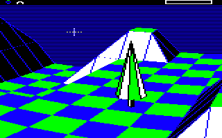
Every polygon has two colours defined in the objPolygonData table, one for the edge and another for the fill colour. A lot of polygon definitions set these to the same colour, so although they technically still have edges, the end result is a single-colour shape. Others have different edge colours, such as the triangles that make up the trees, with their distinctive black outlines:
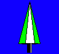
The black edges in the tree's polygons make it stand out nicely from the surrounding landscape, which is important when you only have a palette of four colours to play with:
The problem is that these edges don't look good when the object is small - there just aren't enough pixels to show the edge detail - so the code checks the horizontal distance to the object, which the call to GetObjectAngles put in hypotenuseHi (as well as objectAdjacentHi). If this is greater than or equal to 15 then the object is a fair distance away from the viewer along the z-axis, so we set bit 7 of blendPolygonEdges. This makes the DrawPolygonLines routine draw the polygon edges in the same colour as the polygon body (which is drawn in the fill colour), so the edges blend into the body and the object looks less messy, like the distant trees in this view:
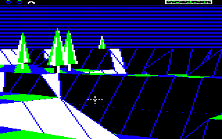
It does mean that distant objects may blend into the background a bit more, but it's less jarring than having a mess of chunky pixelated outlines.
Back-face culling
-----------------
Now that we have the screen coordinates of each of the object's polygons in the drawing tables, the next step is to draw them on-screen. The actual drawing is done by calling the DrawPolygon routine for each polygon, and it's this routine that decides whether or not a particular polygon is visible (i.e. pointing towards the viewer) or hidden (i.e. pointing away from the viewer).
The process of deciding which faces to show is called "back-face culling", and The Sentinel implements this with some very simple logic. This logic is baked into the polygon-drawing routine, which is described in more detail in the deep dive on drawing filled polygons, but essentially this routine works by tracing the edges of the polygon and creating a set of horizontal pixel lines that can then be analysed and drawn correctly. Here's the process:
- First we call the GetPolygonLines routine to generate a set of horizontal polygon lines that we can draw on-screen to display the filled polygon. You can think of these as pixel lines on the screen that together make up the polygon shape.
- If the line-generation process generates a set of horizontal polygon lines where the y-coordinate of the top line is lower down the screen than the y-coordinate of the bottom line, then this means that the polygon must be facing away from us, so we don't draw it (effectively this means the polygon has been flipped in the up-down direction, around the horizontal x-axis, so that it faces away from us). This logic can be found in the GetPolygonLines routine.
- We also test the middle line in the polygon (i.e. the polygon line that's halfway between top and bottom). If the x-coordinate of the middle line's right edge is to the left of the x-coordinate of the left edge, then this means that the polygon must be facing away from us, so we don't draw it (effectively this means the polygon has been flipped in the left-right direction, around the vertical y-axis, so that it faces away from us). This logic can be found in the DrawPolygonLines routine.
Of course, implementing back-face culling in this manner means we effectively have to start drawing the polygon in order to find out whether it is visible, but the advantage is that the checks are simple comparisons, which is considerably simpler than other methods, such as the face normal checks in Elite (see the Elite deep dive on back-face culling for details).
Drawing objects in phases
-------------------------
Back-face culling ensures that polygons that are facing away from the viewer are not drawn, and for simple shapes like the boulder or the Sentinel's tower, that's all we need to make sure the object looks good when we draw those polygons on-screen. However, for more complicated shapes like the meanie and the Sentinel, we need another layer of processing to make sure everything works properly.
When drawing 3D objects, we always draw the polygons in numerical order, so when we draw the boulder, for example, we start with polygon 67 and finish up with polygon 76, as defined by the object's polygon range (see the deep dive on 3D object definitions for details). Unfortunately, for more complex objects in certain positions and orientations, simply drawing all the visible polygons in this order can cause problems. The solution is to draw the object in two phases when this is perceived as a potential issue.
To see what's at stake, let's consider the meanie object, which has the most challenging layout of all the objects in the game. Shaped a bit like an angle-poise lamp, the meanie has its polygons defined in an order that works when drawing the object face-on, i.e. when it is turned towards the camera. Here's what it looks like:
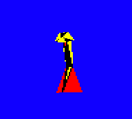
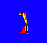
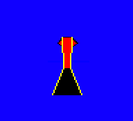
In the first image the meanie is facing towards us and slightly to our left, in the second image it's facing to the left and slightly away from us, and in the third it's facing directly away from us. The first image is drawn with the polygons in the normal polygon order - i.e. starting with polygon 77 and ending with polygon 101 - but in the second and third images the meanie is facing away from the camera, so it is drawn in two phases.
To see why this is necessary, let's consider the last image, where we've turned the meanie around so it is facing directly away from the camera. The meanie has a broad red yellow-edged back that covers up most of the detail, and you can just make out the red-coloured rear of the meanie's head poking out to either side of the yellow-edged back, a bit like ears:
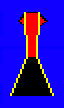
If we look at how this is drawn in slow motion, we can see that the meanie's back is the last detail to be drawn, as it's the closest part to the camera:

What isn't apparent is that this is being drawn in two phases, with everything apart from the meanie's back being drawn first, and then the back being drawn last. If we disable two-phase drawing and try again, then the polygons are drawn in their normal order, and the meanie's head gets turned inside out:
Slowing down the drawing process again shows that with two-phase drawing disabled, the meanie's back gets drawn too soon, before we've had a chance to draw the head, and that leads to a meanie that doesn't look right at all:

So the solution in this case is to change the drawing order of the polygons when the meanie is facing away from the camera, to ensure that the meanie's back gets drawn last rather than in the third step. We do this by splitting the process up into two phases, with the back polygon being drawn in the second phase rather than the first.
In practice there are other polygons that are moved into the second phase as well, to cope with the meanie facing away from us but at an oblique angle, but we can't see those in this specific example as they are pointing away from the camera and aren't drawn in the above animations. But the idea is the same: having two phases lets us change the drawing order to prevent incorrect overlapping of polygons.
Each polygon in the game is therefore given a phase, and the phase determines the order in which the polygons are drawn in each specific object. Most objects are drawn in one phase, but some are drawn in two phases; the number of phases for each object type is defined in the objPolygonPhases table. The number of phases defaults to just one (i.e. draw all the polygons in order), but we switch to two-phase drawing in the following cases:
- We are drawing a meanie and it is facing away from the viewer (as above).
- We are drawing a robot, a sentry or the Sentinel and the object is above the viewer.
The number of phases is calculated in the DrawObject routine and is stored in the drawingPhaseCount variable, which is set to 2 for a two-phase drawing process or 0 for a one-phase drawing process. Then we draw the polygons as follows:
- If we are drawing in one phase, we simply work through the polygons in numerical order and call the DrawPolygon routine for each one, which will draw all the visible polygons in the object.
- If we are drawing in two phases, then we work through the polygons twice. Each polygon has a phase number specified in the objPolygonData table, so on the first pass we draw the polygons that are specified as being in the first phase, and on the second pass we draw the polygons that are specified as being in the second phase. There are only two phases, so this draws all the visible polygons in the object, but in a different order to the one-phase process (though within each phase we still draw polygons in numerical order).
And that's how The Sentinel draws 3D objects from filled polygons, using back-face culling and multi-phase drawing to support more complex structures.