Drawing a partial view of the landscape from back to front
The landscape in The Sentinel is a thing of beauty, and drawing it is a pretty complicated process. Because of this, the drawing isn't done in real-time; a busy landscape may take a couple of seconds to render, as in this example:
In this example the player has just performed a U-turn, so the game redraws the entire landscape view. The player doesn't see the landscape being drawn in-game, however; normally the colours are set to an all-blue palette for the drawing process, so the player just sees a blank blue screen while the game code draws the landscape, and when it's finished the code changes the palette back to the correct colour scheme for the landscape and the updated scene is magically revealed.
If we disable this all-blue palette change to reveal what's going on behind the curtain, then we can see the landscape being drawn, as above. Let's slow it down a bit so we can see it a bit more detail:
You can see that the tiles are drawn from back to front, so the landscape at the front obscures the landscape at the back. Objects are drawn at the same time as the tiles they appear on, and object stacks are drawn in the correct order; in the case of the Sentinel and its tower, the Sentinel is slightly higher than the viewer, so the Sentinel gets drawn first and then the tower.
In this deep dive we'll take a look at this drawing process in detail.
Quadrants and the drawing process
---------------------------------
Before we start, here's a quick note about quadrants. To keep things as simple as possible in this article, I'll only be talking about drawing the landscape in the standard orientation, as shown in the landscape preview:
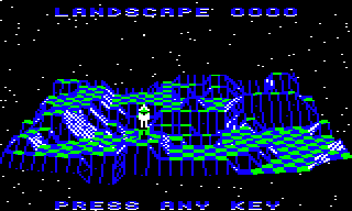
In other words, I'll talk about drawing the view when the viewer is looking towards the back row in this layout (i.e. towards the rear tile row with z-coordinate 30). When viewed in other orientations, the game draws the landscape by applying quadrant corrections to the drawing code, and I've extracted that discussion into its own deep dive on calculating quadrants for the landscape view.
For the purposes of this article, then, we don't need to apply any quadrant corrections to the code, as the landscape preview uses the default quadrant. This means that when I'm talking about the "back row" or "right" and "left", I'm talking about the orientation in the above screenshot. This should keep things nice and simple; they can get a lot more confusing when you have to worry about whether rows are actually columns, and whether the back of the landscape is actually the one on the right...
Note also that the landscape is drawn from the perspective of a specific viewing object (the "viewer"), and this can be set to any 3D object. During gameplay the viewer is always the player, but for the landscape preview we define a completely different camera position by creating an object in space that gazes down on the entire world from a distance, so the whole landscape fits on-screen. See the deep dive on drawing the landscape preview for more details.
A top-level view of the drawing process
---------------------------------------
The landscape is drawn by calling the DrawLandscapeView routine. There's a lot going on in this three-part routine, so let's break down the top-level stages, which we'll look at in more detail below.
- Part 1 of DrawLandscapeView sets up the quadrant variables and calculates the quadrant-relative tile coordinates of the viewer; see the deep dive on calculating quadrants for the landscape view for details.
- Part 2 of DrawLandscapeView works through the landscape and draws one row of tiles and objects at a time, starting from the furthest row (from the perspective of the viewer) to the row just in front of the viewer. It calls a number of routines to do this, including these ones:
- GetTileViewEdges works out the extent of each row of tiles that we need to draw, by working out which tiles are at the right and left edges of the visible part of the row.
- GetTileViewAngles calculates the pitch and yaw angles for each tile corner in the row, relative to the viewer, and whether the corners are on-screen. The angle calculations are explained in the deep dive on converting coordinates to angles.
- DrawLandscapeRow draws a row of tiles between the left visible edge and the right visible edge, drawing it in two parts, one from the left edge towards the viewer and the other from the right edge. It draws each tile (and any objects on the tile) by calling DrawTileAndObjects, which in turn calls the following as required:
- DrawFlatTile to draw a flat tile
- DrawSlopingTile to draw a sloping tile
- DrawTwoFaceTile to draw a tile with a two-faced gully or ridge
- DrawObject to draw a single 3D object on a tile
- DrawObjectStack to draw a stack of 3D objects on a tile
- Part 3 of DrawLandscapeView draws the tile row beneath the viewer, again using the same GetTileViewAngles and DrawLandscapeRow routines as the previous step. The viewer can only see one half of the row, because they are standing on it, so we need to work out which half this is (if they can see any of the row at all) and then draw it. We then draw the tile directly beneath the viewer with a call to DrawFlatTile, and we are done.
For the rest of this article, we're going to take a look at look at the drawing process in parts 2 and 3.
Drawing landscape rows
----------------------
Each tile row in the landscape is drawn in three stages:
- Calculate the row's angles and edges by calling GetTileViewEdges (which calls GetTileViewAngles to get the individual angles).
- Calculate any extra angles we need for the row edges by calling GetTileViewAngles for those edges.
- Draw each tile (and any associated 3D objects) in DrawLandscapeRow.
This process is repeated in part 2 of DrawLandscapeView for each row in front of the viewer, from the furthest row (from the perspective of the viewer) to the nearest, and then we jump to part 3 to draw the viewer's row and we're done.
Let's start by looking at the calculation of the row's angles and edges in GetTileViewEdges. This routine keeps track of a pair of tile numbers in xTileViewLeft and xTileViewRight, which between them contain the numbers of the tile columns that appear at the left and right edges of the screen on the row that we are drawing. For each new row that we draw, the routine takes these left and right column numbers from the previous row and works out whether to extend or reduce the left and right extents of the row edges, depending on whether individual tile corners are on-screen. In this way we can reduce the number of angles that we need to calculate to just those that we need for drawing the visible part of the current row, which saves time as the angle calculations are relatively complicated and slow.
So the first thing we do in GetTileViewEdges is to call GetTileViewAngles to calculate the pitch and yaw angle for the tile corner at the left visible edge of the row we are analysing, i.e. the tile corner at position xTileViewLeft. This routine calculates the following results and stores them in three drawing tables and one variable:
- drawViewYaw(Hi Lo) is the tile corner's yaw angle, stored in the relevant entry in the drawing tables for this tile corner.
- drawViewPitch(Hi Lo) is the tile corner's pitch angle, stored in the relevant entry in the drawing tables for this tile corner.
- tileViewData is the tile data for this tile corner, stored in the relevant entry in the drawing tables for this tile corner.
- tileIsOnScreen is a variable that records whether the tile anchored by this tile corner is off-screen, fully on-screen, or partially on-screen.
The pitch and yaw angle calculations are explained in the deep dive on converting coordinates to angles, and the system of drawing tables is described in the deep dive on the drawing tables.
The tile data is extracted by part 3 of GetTileViewAngles from the tileData table. If the tile is empty and is marked as not being visible in the tile visibility table, then the tile data byte is zeroed before being stored in tileViewData; if the tile contains any objects or is marked as being visible, then the tile data is left alone. This value is used in the drawing process described in the next section, so we don't waste time drawing tiles that can't be seen.
The value of tileIsOnScreen is calculated in part 4 of GetTileViewAngles, but be warned: my analysis of this value seems to be incorrect, and I haven't managed to work out why, so this is on the to-do list to clarify. It shouldn't affect understanding of this process, but it does mean I'm going wave my hands about a bit and pretend that this all makes perfect sense, while some of the specific implementation details are a little bit in flux.
Now that we have calculated the angles, tile data and on-screen status for the current tile corner, the GetTileViewEdges routine effectively "feels" its way left and right along the row, and each time it moves along the line, it calls GetTileViewAngles again to fetch the angles, tile data and on-screen data for that corner. It then uses this information to continue moving along the row, updating xTileViewLeft or xTileViewRight as required. I confess that I don't fully understand this algorithm, but that's probably because I've got the values of tileIsOnScreen wrong; but the idea is to find the left and right extents of the on-screen portion of the row in a manner that calculates the angles for all the visible tile corners, at the same time as minimising the number of angles that we need to calculate.
On returning back to part 2 of DrawLandscapeView from the GetTileViewEdges routine, we check the calculated left and right extents of the visible part of the row that we just calculated, to make sure that we have four calculated sets of angles for each of the tiles that we need to draw. This process starts at dlan7. We do this because as we move forwards through the landscape, the new row of corners might have a wider extent than the previous row, which would mean the tiles at the edges might not have both of the tile's far corners stashed in the drawing tables from the previous row's calculations, and this would mean we couldn't draw those tiles. So we check the left and right extents at dlan9 and dlan13 to ensure that the tiles at each end have all four angles cached, and then we are finally ready to move on to the actual drawing process at dlan15.
Drawing tiles
-------------
Once all the angles have been calculated and all the tile data extracted for each tile corner in the visible part of the current row, we can actually draw the row on-screen by calling DrawLandscapeRow. This simple routine draws a row of tiles between the left visible edge and the right visible edge, drawing it in two parts, one from the left edge towards the left side of the viewer, and the other from the right edge towards the right side of the viewer. This ensures that more distant tiles are drawn before nearer ones, all from the perspective of the viewer.
You can see each row of tiles being drawn in two parts in this slowed-down clip of the landscape preview being drawn:
Because the viewer (in this case, the camera) is lined up with the middle of the landscape, the drawing process starts by drawing each tile row from the left edge of the landscape towards the viewer in the middle, and then it draws the other half of the row from the right edge of the landscape towards the viewer in the middle.
Each individual tile is drawn by calling the DrawTileAndObjects routine. This starts by checking the relevant tile data from the tileViewData drawing table, which will be zero if this tile is empty and is not visible (in which case we abort the drawing process). If it is non-zero then we can then extract the tile shape from the tile data and decide how to draw the tile.
If the tile contains any objects, then we draw both the tile and the object stack by calling DrawObject or DrawObjectStack. The drawing process for object stacks is described in the deep dive on stacking objects, but essentially the object stack is drawn in a similar manner to the landscape, with more distant objects being drawn before nearer objects, and with the tile being drawn at the correct point as well.
One thing that is worth noting is that tiles containing objects ignore the tile's setting in the tile visibility table, so we always draw tiles with objects on them, even if those tiles are not visible. This is because object stacks can be really high, so even if the tile is hidden, the top of the object stack may be visible for miles around, so we always draw the stack. Here's an example with a tree just poking above the furthest part of the landscape:
And here's another couple of trees being drawn on tiles that are obscured, but with large parts of the objects being visible:
And as an extreme example, here's a tree being drawn and then being completely obscured:
which you can see a bit more clearly when you slow things down:
That's what happens for tiles containing objects, but for empty tiles, we choose the correct routine to draw the specific tile shape, as follows:
- DrawFlatTile draws a flat tile by calling DrawOneFaceTile.
- DrawSlopingTile draws a sloping tile, which can have either one or two faces. If the tile shape has one face, then this is drawn by calling DrawOneFaceTile, and if it has two then we call DrawTwoFaceTile.
These routines draw each individual tile face by calling the DrawPolygon routine, which draws the polygons for the faces using the angles of the relevant tile corners from the drawing tables; see the deep dive on drawing filled polygons for details. The number of sides in the polygon is passed via the polygonType parameter, while the polygon's colours are passed to the routine via the polygonColours parameter.
The number of sides is easy to work out from the tile shape: flat and one-face sloping tiles have one slope with four sides, while all other shapes consist of two triangles (see the deep dive on tile shapes for details). Most of the work in the above routines therefore goes into calculating the correct colours for the polygons, and the correct starting points for the various triangles.
The simplest option is for flat tiles, where we set a tile's colour according to where it is in the chess board pattern. If both of the tile's x- and z-coordinates are even or odd, then the tile is drawn in colour 3 (which is white in the examples shown here), otherwise the tile is drawn in blue.
Things are rather more complicated for other shapes. The colours of the individual faces in each tile shape are defined in the tileShapeColour table, which defines two colours for each shape. For one-sided shapes only one colour is used, and for all shapes the colours are chosen according to the direction in which the viewer is looking. This ensures that sloping faces get drawn in consistent colours, so in the following example, faces that look to the right are always drawn in black, while faces that look to the left are always drawn in white:
The logic for choosing the correct colours depending on the viewing direction can be found in the latter part of the DrawSlopingTile routine, after which DrawTwoFaceTile draws the first polygon in the specified colour from tileShapeColour, followed by the second polygon in the other colour from tileShapeColour. This logic is documented but it doesn't really explain why the algorithm works, so this is another item on the to-do list to improve.
Drawing the row beneath the viewer
----------------------------------
The final part of the process is to draw the row beneath the viewer, which we do in Part 3 of DrawLandscapeView. We only jump here if we reach the row containing the viewer, by which point all the rows in front of the viewer will have been drawn in part 2. We may never reach the viewer's row - as in the landscape preview, for example - in which case we simply iterate through all 31 rows in part 2 before terminating there.
The viewer can only see one half of the row, because they are standing on it and can't look along it in both directions at once, so first we need to work out which half this is (if they can see any of the row at all) and then draw it (or skip to the next stage if it isn't visible). We can do this fairly quickly by comparing the viewer's tile coordinates with the left and right extents of the tile row to see if the visible part of the row extends beyond the viewer's tile.
Once the row has been analysed, we next ensure that we have all the angles that we need for both ends of this half tile row, by calling GetTileViewAngles for each edge. We then draw the row with a call to DrawLandscapeRow.
All that remains now is to draw the tile beneath the viewer, so first we make sure we have the angles for the two tile corners in front of the viewer, so by this point we have the following:
- The tables at drawViewYaw+0 and drawViewPitch+0 contain data for the tile corner row in front of the viewer, i.e. for the front edge of the tile on which the viewer sits.
- The tables at drawViewYaw+32 and drawViewPitch+32 contain data for the tile corner row containing the viewer, i.e. for the rear edge of the tile on which the viewer sits.
If Y is the offset of the viewer's tile within these tables, then we now have this setup, for example:
- drawViewPitchHi,Y is the corner at the front left of the viewer's tile.
- drawViewPitchHi+1,Y is the corner at the front right of the viewer's tile.
- drawViewPitchHi+32,Y is the corner at the rear left of the viewer's tile.
- drawViewPitchHi+32+1,Y is the corner at the rear right of the viewer's tile.
We now set up these angles for the tile to ensure that it looks correct, by straightening out the two front corners of the tile so that they are horizontally level, and we position the corners of the viewer's tile so it spreads to the left and right screen edges and appears to dip down behind the viewer (so it spreads down to the bottom of the screen as well).
As the very last step in drawing the landscape, we draw the tile under the viewer with a call to DrawFlatTile, and we are finally done.
And that's why it takes more than a blink of an eye to draw the landscape view; it's complicated stuff!