Drawing colourfully filled triangles and quadrilaterals on-screen
The Sentinel's landscape is a thing of beauty, with its slopes and trees and chess-board tiles:
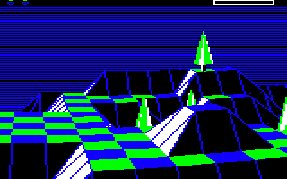
There is a surprise in this tranquil scene, though. If you ignore the top row with the energy icons and scanner, and the lined sky-blue background, then absolutely everything else in the landscape view is drawn as filled polygons, and that's it. There is no line-drawing routine in The Sentinel, there is only the polygon-drawing routine, and that does all the heavy lifting, even for the parts of the landscape that look like they're made up of lines.
Let's see how The Sentinel draws these filled polygons.
The DrawPolygon routine
-----------------------
The DrawPolygon routine is the core drawing routine in The Sentinel. It can draw four different types of polygon, as follows:
| Type | Called by | Description | Sides |
|---|---|---|---|
| One-face tile quadrilateral | DrawOneFaceTile | Used to draw landscape tiles with one face, such as flat tiles or tiles with one sloping side | 4 |
| Two-face tile triangle | DrawTwoFaceTile | Used to draw landscape tiles with two faces, such as gullies | 3 |
| Object polygon | DrawObject | Used to draw 3D objects | 3, 4 |
The type of polygon to draw is passed to the DrawPolygon routine in the polygonType parameter. In the case of two-face tiles, these are drawn by calling DrawPolygon twice, once for each triangular face, and with a different type for the first and second triangles. In all cases the pitch and yaw angles for the individual polygon points are passed to the routine via the relevant drawing tables: for tile faces the points should be from offsets 0 and 32 of the drawing tables, with one set for each of the two rows of tile corners that between them define the tiles in that row; while for object polygon points, the angles should be from offset 64 in the drawing tables. See the deep dive on the drawing tables for details on how the drawing tables work.
The DrawPolygon routine draws polygons using a two-stage process, which we'll look at in detail over the course of this article:
- First the GetPolygonLines routine is called to calculate the horizontal "polygon lines" that make up the filled polygon. It does this by tracing the polygon outline in the TracePolygonEdge routine. It then projects them from pitch and yaw angles into screen coordinates (see the deep dive on the projection system for details).
- Then the DrawPolygonLines routine is called to actually draw those polygon lines onto the screen or into the screen buffer.
On top of this, if we are drawing into a row buffer (which we do when drawing the entire screen, or when panning the screen up or down), then DrawPolygon splits the polygon-drawing process further. Each character row in screen memory is 320 bytes wide, and the DrawPolygon routine splits this up into two parts: the first 256 bytes of each character row, and the last 64 bytes of each character row. The routine then draws the relevant bits of the polygon into the first part of screen memory, and then it draws any bits of the polygon that are in the second part.
The reason for doing this is that each polygon line is stored as a pair of screen x-coordinates denoting the start and end coordinate of the horizontal line on each screen y-coordinate (i.e. on each pixel line on the screen). These x-coordinates are stored as single bytes in the xPolygonLeft and xPolygonRight tables, so the width of each polygon line in these tables can't be more than 256 x-coordinates, even though the maximum width of each polygon is 320 x-coordinates (note that at this stage the coordinates are calculated to a screen width of 320 x-coordinates, even though the screen is only 160 pixels wide). We therefore draw the polygon in two parts to ensure it fits within the tables.
Let's take look at these two stages of drawing polygons, starting with the more complex of the two: the calculation of the horizontal polygon lines.
Calculating polygon lines
-------------------------
The aim of the GetPolygonLines routine is to calculate the "polygon lines" for the polygon we want to draw. The polygon lines are the horizontal pixel lines that make up the filled polygon on-screen, and they are stored in the xPolygonLeft and xPolygonRight tables. The values at offset Y in each table give us the x-coordinates of the left and right ends of the polygon line that we need to draw on the Y-th pixel line on the screen. These values are only calculated for lines that make up the polygon; we ignore anything that's above or below the polygon. Once calculated, the polygon lines can then be drawn by the DrawPolygonLines routine.
There are quite a few stages in the six-part GetPolygonLines routine, with a further eight parts in the TracePolygonEdge routine, and things are made even more complicated by the use of self-modifying code, which is always a challenge to analyse. Let's summarise the process.
- Before calling GetPolygonLines, we populate the drawing tables with the pitch and yaw angles of all the points that we need for the drawing process, and we set drawViewAngles(1 0) to the address of the list of point numbers in the polygon. Here are the details:
- When drawing the landscape, we populate the drawing tables with the angles for all the visible tile corners for the tile row we are drawing, and we set drawViewAngles(1 0) to the address of polygonPoint (which we will populate with the indexes of the points for the polygon that we are drawing, in the next step in the GetPolygonLines routine). See the deep dive on drawing the landscape view for details.
- When drawing 3D objects, we populate the drawing tables from offset 64 with the angles for the object points in this object, and we set drawViewAngles(1 0) to the address of the relevant objPolygon label within the object definition (i.e. to one of objPolygon000 through objPolygon151). These contain the point numbers for the specified polygon, which we can use as indexes into the drawing tables; the point numbers have 64 added to them in the objPolygon tables to ensure the polygon angles are taken from offset 64 within the drawing tables. See the deep dive on calculating angles for drawing 3D objects for details.
- We now call the GetPolygonLines routine at its entry point in part 2 and set up the polygonPoint block as follows:
- If we are drawing a quadrilateral polygon when drawing a one-face tile, then we populate the five bytes at polygonPoint with the drawing table offsets for the four points in the polygon as follows:
  1. Rear left       4. Rear right

  2. Front left      3. Front right
We also set point 5 to be the same as point 1, so that the fourth edge from point 4 to point 5 is effectively from point 4 to point 1. - If we are drawing a triangle polygon as part of a two-face tile, then we jump to part 1 of GetPolygonLines to populate the four bytes at polygonPoint for the triangle. Points 1 and 2 are set up in the same way as with the quadrilateral above, and we also set point 4 to be the same as point 1, so that the third edge from point 3 to point 4 is effectively from point 3 to point 1. Point 3 can be one of four options: either of the two points to the right of the first two, or either of the two points to the left of the first two. So if we have already chosen points 1 and 2, then the third triangle point is one of [a] to [d], as follows:
  [d]    [1]    [a]

  [c]    [2]    [b]
The third point is chosen by adding an entry from the trianglePointAdd lookup table to the offset for point 2. For the first triangle in the two-face tile, we choose either [a] or [b], according to the value of triangleStartPoint (which is set in either DrawTileAndObjects or DrawSlopingTile to 0 or 1). For the second triangle we choose the corner that's diagonally opposite the one we chose for the first triangle, so that's [c] if the first triangle used [a], or [d] if the first triangle used [b]. - If we are drawing an object polygon, we don't need to populate polygonPoint, as we're using the hard-coded objPolygon data for our point indexes instead.
- If we are drawing a quadrilateral polygon when drawing a one-face tile, then we populate the five bytes at polygonPoint with the drawing table offsets for the four points in the polygon as follows:
- Once the polygon points have been chosen and the indexes have been set up in polygonPoint, we jump to part 4 of GetPolygonLines to fetch all the relevant polygon point yaw angles from the drawing tables and convert them into pixel x-coordinates using projection (for details see the deep dive on the projection system). In this particular conversion process, screen x-coordinates can be anywhere in the range 0 to 319, so some polygons can therefore have x-coordinates that are 256 or greater; for these polygons we project the results into two-byte x-coordinates using the calculations in part 3 of GetPolygonLines. For polygons that fit into the x-coordinate range 0 to 255, we use the simpler calculation in part 4. The projected coordinates are stored in the xPolygonPointHi and xPolygonPointLo tables (though the high byte is only used when we need to use two-byte coordinates).
- The final step in part 5 of GetPolygonLines is to loop through all the edges in the polygon and call the TracePolygonEdge routine for each one. This routine works out the coordinates of the left and right edges of the polygon, storing the results in the xPolygonLeft and xPolygonRight tables. Part 5 looks after this process for one-byte x-coordinates while part 6 does the calculations for two-byte x-coordinates.
Let's talk about that last step a bit more. The edge-tracing process is done by the TracePolygonEdge routine, and there are a lot of different parts to this routine: eight, to be exact. That's because it contains different routines that are optimised to trace different angles of polygon edge, and it also needs to cope with both one-byte and two-byte x-coordinates, as well as edges that are only partially on-screen.
For the routine to work, the start point must have a bigger y-coordinate than the end point, so the edge is either horizontal or slopes downwards when tracing the edge from start to end. Each part implements a subtly different algorithm to apply to each edge, and the logic works as follows:
- Part 1: Analyse the edge slope, initialise the variables and decide which of the following algorithms to apply.
- Part 2: Trace a polygon edge with a steep gradient by stepping along the y-axis.
- Part 3: Trace a polygon edge with a shallow gradient by stepping along the x-axis.
- Part 4: Trace a steep edge that starts off-screen, without storing the coordinates, until we reach the screen and return to part 2.
- Part 5: Trace a shallow edge that starts off-screen, without storing the coordinates, until we reach the screen and return to part 3.
- Part 6: Trace a polygon edge where the start or end point x-coordinates are two-byte numbers.
- Part 7: Trace a polygon edge with a steep gradient by stepping along the y-axis (for two-byte x-coordinates).
- Part 8: Trace a polygon edge with a shallow gradient by stepping along the x-axis (for two-byte x-coordinates).
This process will be familiar to anyone who has analysed a line-drawing routine on 8-bit computers. In a sense the polygon is traced by drawing each of the polygon's edges, but instead of poking the results into screen memory, we simply make a note of the coordinates for each pixel line and store them in either the xPolygonLeft and xPolygonRight table (the table to use for the result is determined by the value of xPolygonAddrHi when the routine is called, which is set to the high byte of either the left or right table).
Once we have calculated the polygon lines, we move on to the drawing process, so let's have a look at that next.
Drawing polygon lines
---------------------
Compared to the calculations for the polygon lines, the drawing routine in DrawPolygonLines is relatively straightforward, though its use of self-modifying code can make it a little hard to follow.
Part 1 is all about preparation, with various calculations that work out the correct screen addresses to use within the screen or screen buffer. We also set up the drawing variables and modify the code into the correct starting configuration.
If bit 7 of blendPolygonEdges is set, then the routine is configured not to draw polygon edges in different colours, so we set the edge colour to be the same colour as the polygon body (i.e. we set it to be the same as the fill colour). This makes the edges blend into the body, which we want to do for distant objects (see the deep dive on drawing 3D objects for details).
Once everything is configured, we jump to part 3 to start the drawing. The drawing loop spans parts 2, 3 and 4, and part 3 draws the left and right edges of the polygon line, ensuring the line fits within the screen buffer we are drawing into (see the next section), and making sure to merge the results into the existing screen contents along the edges. We then fall into part 4 to draw the horizontal line between the two edges using an unrolled loop of store operations into which we jump using a modified branch instruction. This ensures that we draw the correct number of pixel bytes, drawing from right to left, starting from the branch entry point and drawing to the left end of the line. Interestingly, this approach is inherited from the track-drawing routines in Revs, which features a similar list of unrolled drawing code into which we jump to draw the correct length of horizontal line; see the Revs deep dive on drawing the track view for details.
Once the line has been drawn, we loop back to part 2 to move on to the next polygon line, moving down into a new character row if required. We also analyse the line to see if it's overflowing the sides of the buffer, and if it is we set either the polygonGoesLeft or polygonGoesRight variables so the DrawPolygon routine can decide whether it needs to draw a second part of the polygon, Finally, we check whether the new line fits into one pixel byte, in which case we draw it, otherwise we fall into part 3 to draw the line in full.
This process gets repeated for every polygon line in the polygon, until we have drawn a filled 3D polygon onto the screen.
Clipping polygons
-----------------
You may be wondering how The Sentinel clips all its lines and polygons to fit the shape of the current screen buffer, so it can draw them cleanly and without spilling over into neighbouring memory outside the screen buffer. Elite, for example, has a sophisticated line-clipping routine that takes line coordinates, some of which may be off-screen, and calculates the coordinates of any on-screen portions before passing them on to the line-drawing routines (see the Elite deep dive on line-clipping for details). So where is the equivalent in The Sentinel?
Well, there isn't one, at least not in the sophisticated manner in which Elite clips its lines. This is perhaps not that surprising, because as we mentioned above, absolutely everything you see in the landscape view in The Sentinel is a polygon. It sometimes looks like there are lines, but they aren't actually lines; every single shape, from tiles to robots, is a polygon.
As we've also seen, all these polygons - even those that are only partially on-screen - are drawn by tracing the polygon's outline and producing a set of horizontal polygon lines, each of which is stored as a left and right x-coordinate for each particular y-coordinate.
It's at this point that the horizontal polygon lines are drawn. As part of the drawing code, we check whether the line goes past the left or right edges of the screen buffer, so that we can do things like drawing wide objects in two halves. And this bit of code doubles as a clipping mechanism, because if the line does go past the edge of the screen buffer, we simply update the x-coordinate for that end of the line to match the edge of the buffer, so we only draw the part of the line that is inside the buffer.
That's it - it's not really an algorithm in the sense of Elite's sophisticated line-clipping process, it's just a simple application of maximum and minimum values to the x-coordinates. Here's where this "clipping" process is done:
- The left and right edges of each polygon line are drawn in part 3 of DrawPolygonLines at dpol15, which checks the coordinates against the edges of the screen buffer.
- If the right end of the polygon line goes past the right edge of the buffer, it is clipped at dpol7 in part 2 of DrawPolygonLines.
- If the left end of the polygon line goes past the left edge of the buffer, it is clipped at dpol8 in part 2 of DrawPolygonLines.
And that's it; as clipping processes go, it's about as simple as it gets.
Back-face culling
-----------------
One thing I've left out of the above description is the sequence of checks that are performed by the GetPolygonLines and DrawPolygonLines routines to catch any polygons that we shouldn't be drawing. For example, we don't want to draw any polygons that face away from the viewer, as we don't want to be able to see the insides of 3D objects or the internals of the 3D landscape (this is known as "back-face culling", and is discussed in the deep dive on drawing 3D objects).
The most obvious of these checks is in the use of the drawPolygon variable, which is set to a non-zero value in part 5 of GetPolygonLines, just before we start tracing the polygon edges. If at any point the calculations generate a polygon line that contains pixels, then drawPolygon is zeroed, so by the end of the GetPolygonLines routine, a zero value of drawPolygon indicates that there is at least one polygon line to draw (and conversely, a non-zero value means this polygon has nothing to draw, so we can abort the drawing process at this point).
Another test at the end of the GetPolygonLines routine checks whether the top of the polygon is higher than the bottom of the polygon. This is a simple comparison of the y-coordinate of the top line and the y-coordinate of the bottom line; if the top line is lower down the screen than the bottom line, then this means that the polygon must be facing away from us, so we don't draw it (effectively this means the polygon has been flipped in the up-down direction, around the horizontal x-axis, so that it faces away from us).
Finally, the DrawPolygonLines tests the middle line in the polygon (i.e. the polygon line that's halfway between top and bottom). If the x-coordinate of the middle line's right edge is to the left of the x-coordinate of the left edge, then this means that the polygon must be facing away from us, so we don't draw it (effectively this means the polygon has been flipped in the left-right direction, around the vertical y-axis, so that it faces away from us). This logic can be found at the start of the DrawPolygonLines routine.
And that's how the 3D landscape in The Sentinel comes to life, with back-face culling, filled polygons and a complete absence of line-drawing routines.